
Lab 3.4 - VLAN Theory: 802.1Q Tagging, Access and Trunk Ports

Introduction
Labs 3.1 to 3.3 connected routers across a WAN. Every host in those labs sat on a subnet that belonged to exactly one router interface, and each router handled the traffic between subnets. That model is simple, but it assumes that one physical port equals one network. A real site rarely works that way. A single switch may carry a staff network, a guest network, a voice network, and a management network, and each must stay separate even though the same cables and the same switch carry them all.
A Virtual LAN (VLAN) solves this by dividing one physical switch into several logical broadcast domains. Hosts in VLAN 10 and hosts in VLAN 20 cannot exchange Ethernet frames directly, even when they are plugged into the same switch, unless a router connects them. The mechanism that makes this possible across a single cable is IEEE 802.1Q. It inserts a four-byte tag into each Ethernet frame that says which VLAN the frame belongs to. Ports are then configured in one of two roles: an access port that carries one VLAN untagged toward an end host, and a trunk port that carries many VLANs tagged between switches or between a switch and a router.
This lab is a theory lab. You will build a small Layer 2 network on two RouterOS devices acting as switches, using a bridge with VLAN filtering enabled. You will see how an access port hides the tag from the host, how a trunk carries several VLANs over one link, and what happens when the two ends of a link disagree about which frames are tagged. The routing between VLANs, the QinQ stacking, and the switch-chip offload are left for later labs in Module 3.
Work through the steps in order. The configuration is built up gradually, and each step is verified before the next one changes the network.
Terminology Definitions
VLAN (Virtual LAN): A logical broadcast domain created on a switch. Frames inside one VLAN are forwarded only to ports that belong to that VLAN. Hosts in different VLANs are isolated at Layer 2 and communicate only through a router.
Broadcast Domain: The set of devices that receive each other's broadcast frames. Each VLAN is a separate broadcast domain, so ARP requests and DHCP discovery stay inside it.
IEEE 802.1Q: The standard that defines VLAN tagging on Ethernet. It inserts a four-byte tag after the source MAC address, carrying the Tag Protocol Identifier (TPID, value 0x8100) and a Tag Control Information (TCI) field.
VLAN ID (VID): The 12-bit field in the 802.1Q tag that identifies the VLAN. Valid values are 1 to 4094. VLAN 0 means priority-tagged only, and 4095 is reserved.
Tagged Frame: An Ethernet frame that carries an 802.1Q tag, so the receiving device knows which VLAN it belongs to.
Untagged Frame: An Ethernet frame without an 802.1Q tag. The VLAN for an untagged frame is determined by the port on which it arrives.
Access Port: A switch port that belongs to a single VLAN and carries frames untagged toward the end host. The host never sees a tag and needs no VLAN awareness.
Trunk Port: A switch port that carries frames from several VLANs, each tagged with its VID, so that a single link can carry many VLANs between two devices.
PVID (Port VLAN ID): The VLAN assigned to untagged frames that arrive on a port. On an access port, the PVID is the port's VLAN. In RouterOS this is set with the pvid property on a bridge port.
Native VLAN: The VLAN whose frames cross a trunk untagged. Both ends of a trunk must agree on the native VLAN, or untagged frames are delivered to the wrong VLAN. This lab keeps the native VLAN at its default and places all traffic on tagged VLANs on the trunk.
Bridge VLAN Filtering: The RouterOS feature that makes a bridge VLAN-aware. When it is enabled on a bridge, each port is checked against the bridge VLAN table, and frames in a VLAN the port does not belong to are dropped.
Frame Types: A bridge port setting that controls which ingress frames a port accepts: admit-all, admit-only-vlan-tagged, or admit-only-untagged-and-priority-tagged.
Lab Topology
R1 and R2 are used as Layer 2 switches. Each has a bridge with VLAN filtering enabled. ether1 on each router is a trunk between them. ether2 and ether3 on each router are access ports. Four VPCs act as end hosts: two in VLAN 10 and two in VLAN 20. R3 is not used in this lab.
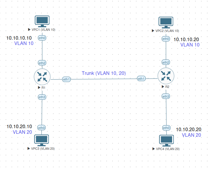
The trunk carries both VLANs between R1 and R2, and each access port delivers one VLAN to a host. No IP addresses are configured on the routers. The routers forward frames only at Layer 2, so every test in this lab is a test of the VLAN configuration, not of routing.
Network summary:
| Device | Port | Mode | VLAN | Host address |
|---|---|---|---|---|
| R1 | ether1 | Trunk | 10, 20 tagged | none |
| R1 | ether2 | Access | 10 | VPC1 10.10.10.10/24 |
| R1 | ether3 | Access | 20 | VPC3 10.10.20.10/24 |
| R2 | ether1 | Trunk | 10, 20 tagged | none |
| R2 | ether2 | Access | 10 | VPC2 10.10.10.20/24 |
| R2 | ether3 | Access | 20 | VPC4 10.10.20.20/24 |
VLAN plan:
| VLAN ID | Name | Subnet | Hosts |
|---|---|---|---|
| 10 | Staff | 10.10.10.0/24 | VPC1, VPC2 |
| 20 | Guest | 10.10.20.0/24 | VPC3, VPC4 |
Prerequisites and Starting Configuration
Start from routers with no tunnels, OSPF instances, or static routes left over from Lab 3.3. Remove any IP addresses on ether1 to ether3 from earlier labs, since this lab uses the routers at Layer 2 only.
Important: Enabling VLAN filtering on the bridge can interrupt any management connection that passes through a bridge port. Perform this lab from the EVE-NG console of each router, not from a Winbox or SSH session that runs over ether1 to ether3.
Complete Starting Configuration
Configure VPC1:
set pcname VPC1
ip 10.10.10.10 255.255.255.0
save
Configure VPC2:
set pcname VPC2
ip 10.10.10.20 255.255.255.0
save
Configure VPC3:
set pcname VPC3
ip 10.10.20.10 255.255.255.0
save
Configure VPC4:
set pcname VPC4
ip 10.10.20.20 255.255.255.0
save
The VPCs have no gateway. There is no router in this lab that routes between VLANs, so the VPCs have no reason to use one.
Verification:
Confirm that each router is clean before you begin:
/interface bridge print
/ip address print
Both should show no entries for this lab. Neither router has a bridge or an address on ether1 to ether3.
Lab Exercises: VLAN Theory
Step 1: Why One Switch Is Not Enough
Before configuring anything, consider a single switch with four hosts and no VLANs. All four ports belong to one broadcast domain. A broadcast from VPC1 reaches VPC2, VPC3, and VPC4. A host in the guest network can see ARP traffic from the staff network and can attempt to talk to staff hosts directly. Separating the two networks with a second physical switch works, but it doubles the hardware, and it still needs a second cable run for every additional network.
A VLAN keeps the logical separation without the extra hardware. The switch treats each VLAN as its own switch. Frames are forwarded only within their VLAN, and the trunk between two switches carries every VLAN over a single cable. The cost is that the switches must agree on which frame belongs to which VLAN, and that is what the 802.1Q tag provides.
The lab is designed so that the two problems can be observed directly. Without VLANs, the four hosts can all reach each other. With VLANs, the staff hosts reach each other and the guest hosts reach each other, but staff and guest traffic does not cross.
Step 2: The 802.1Q Tag
An untagged Ethernet frame has a destination MAC, a source MAC, an EtherType, and a payload. An 802.1Q tagged frame has the same fields with a four-byte tag inserted between the source MAC and the EtherType:
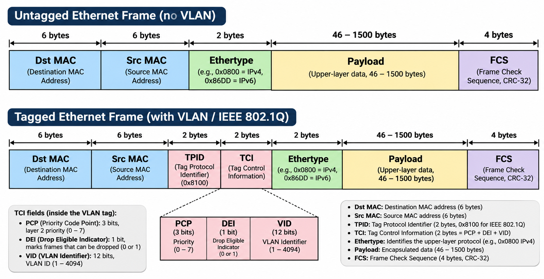
The TPID and TCI fields are as follows:
| Field | Size | Purpose |
|---|---|---|
| TPID | 16 bits | Always 0x8100 for 802.1Q. It tells the receiver that a tag follows. |
| PCP (priority) | 3 bits | Class of service, used for QoS. |
| DEI (drop eligible) | 1 bit | Marks frames that may be dropped first under congestion. |
| VID (VLAN ID) | 12 bits | The VLAN the frame belongs to, 1 to 4094. |
Two consequences follow from the format. First, the tag adds four bytes, so a frame on a trunk can be 1522 bytes instead of 1518. Some switches and interfaces must be configured to accept the larger frame, or the tagged traffic is dropped. Second, the VID is the only thing that determines the VLAN of a tagged frame. The port on which the frame arrives does not matter once the tag is read.
A tagged frame and an untagged frame are handled differently at each port type, and the rest of the lab depends on that difference.
Step 3: Building the Bridge with VLAN Filtering
RouterOS implements VLAN switching inside a bridge. Create a bridge on each router and turn on VLAN filtering. Without the vlan-filtering setting, the bridge ignores VLAN tags and behaves as a single broadcast domain.
On R1:
/interface bridge add name=bridge1 vlan-filtering=yes comment="VLAN switch"
On R2:
/interface bridge add name=bridge1 vlan-filtering=yes comment="VLAN switch"
Check that the bridge exists and that filtering is on:
/interface bridge print
The vlan-filtering column should show yes.
Next, add the ports. A port is added to the bridge with a frame type and, for access ports, a PVID.
On R1:
/interface bridge port add bridge=bridge1 interface=ether1 frame-types=admit-only-vlan-tagged comment="trunk to R2"
/interface bridge port add bridge=bridge1 interface=ether2 pvid=10 frame-types=admit-only-untagged-and-priority-tagged comment="access VLAN 10"
/interface bridge port add bridge=bridge1 interface=ether3 pvid=20 frame-types=admit-only-untagged-and-priority-tagged comment="access VLAN 20"
On R2:
/interface bridge port add bridge=bridge1 interface=ether1 frame-types=admit-only-vlan-tagged comment="trunk to R1"
/interface bridge port add bridge=bridge1 interface=ether2 pvid=10 frame-types=admit-only-untagged-and-priority-tagged comment="access VLAN 10"
/interface bridge port add bridge=bridge1 interface=ether3 pvid=20 frame-types=admit-only-untagged-and-priority-tagged comment="access VLAN 20"
The two frame types do different jobs:
admit-only-vlan-taggedon the trunk. The trunk accepts only tagged frames. An untagged frame arriving from the far switch is dropped, which is intended, because every frame on the trunk should name its VLAN.admit-only-untagged-and-priority-taggedon the access ports. The access port accepts untagged frames from the host and frames with VLAN 0 (priority tag only). A frame that arrives tagged with a real VID, such as VLAN 20 on the VLAN 10 port, is dropped. The host cannot choose its own VLAN.
The pvid on each access port assigns the port's VLAN to frames that arrive untagged from the host. Tagged frames are not affected by the PVID.
Verify the port table on each router:
/interface bridge port print
Each port should show the bridge, the frame type, and the PVID you set. Ports ether2 and ether3 should show pvid=10 and pvid=20 respectively.
Step 4: Defining the VLANs and Tagging the Trunk
The port table decides how frames enter and leave each port. The bridge VLAN table decides which VLANs each port belongs to and whether it sends them tagged or untagged. Add the VLAN entries now.
On R1:
/interface bridge vlan add bridge=bridge1 vlan-ids=10 tagged=ether1 untagged=ether2 comment="Staff"
/interface bridge vlan add bridge=bridge1 vlan-ids=20 tagged=ether1 untagged=ether3 comment="Guest"
On R2:
/interface bridge vlan add bridge=bridge1 vlan-ids=10 tagged=ether1 untagged=ether2 comment="Staff"
/interface bridge vlan add bridge=bridge1 vlan-ids=20 tagged=ether1 untagged=ether3 comment="Guest"
Read each line as a statement about the port's role in that VLAN:
tagged=ether1means ether1 carries VLAN 10 and VLAN 20 with the 802.1Q tag. That is the trunk role.untagged=ether2means ether2 delivers VLAN 10 to its host without a tag. That is the access role.
The same VLAN can be tagged on one port and untagged on another, and this is the core of the design. A VLAN is a property of each port's membership, not of the VLAN as a whole.
Verify the table:
/interface bridge vlan print
Each VLAN should list its tagged and untagged ports as above.
Confirm that the trunk ports carry only the expected VLANs:
/interface bridge vlan print where vlan-ids=10
/interface bridge vlan print where vlan-ids=20
Step 5: Testing Same-VLAN and Cross-VLAN Reachability
With the bridges, ports, and VLAN table in place, the network can now be tested from the hosts. Start with the same VLAN across the trunk.
From VPC1 (VLAN 10 on R1), ping VPC2 (VLAN 10 on R2):
ping 10.10.10.20 -c 4
This should succeed. VPC1 sends an untagged frame to ether2 on R1. R1 assigns VLAN 10 through the PVID, sends the frame tagged with VID 10 out ether1, and R2 receives it on ether1, reads VID 10, and delivers it untagged out ether2 to VPC2. The reply follows the same path in reverse.
Now test across the two VLANs. From VPC1 (VLAN 10), ping VPC3 (VLAN 20 on R1), which sits on the same switch:
ping 10.10.20.10 -c 4
This should fail. The two hosts are on the same switch but in different broadcast domains. VPC1 sends an ARP request for 10.10.20.10 on VLAN 10, and the request is not delivered to any VLAN 20 port. There is no router in the lab to bridge the two, so the ping gets no reply.
Confirm the cause on R1 by checking the bridge host table:
/interface bridge host print
The host table lists the MAC addresses learned on each VLAN. VPC1's MAC should appear in VLAN 10 only, and VPC3's MAC should appear in VLAN 20 only.
Finally, test the guest VLAN across the trunk. From VPC3 (VLAN 20 on R1), ping VPC4 (VLAN 20 on R2):
ping 10.10.20.20 -c 4
This should succeed, and it is the mirror image of the staff test. The guest VLAN also spans the trunk, and the same tag carries it to R2.
Step 6: Trunk and Access Ports Compared
A trunk and an access port can both belong to a VLAN, and they differ in what they do with the tag. The table below summarises the behaviour that you have configured and observed.
| Property | Access port | Trunk port |
|---|---|---|
| Number of VLANs carried | One (the PVID) | Many, listed in tagged= |
| Frames to the host or far switch | Untagged | Tagged with the VID |
| Frames from the host or far switch | Untagged frames take the PVID | Tagged frames keep their VID |
| Typical frame type | admit-only-untagged-and-priority-tagged |
admit-only-vlan-tagged |
| Connected to | End host, printer, camera, phone | Another switch, or a router with VLAN subinterfaces |
| Host awareness of VLANs | None | Device must understand 802.1Q |
The access port is the reason a PC works without any VLAN configuration. The trunk is the reason one cable can carry all the VLANs between two switches. Both use the same bridge VLAN table, so the difference is entirely in how each port is configured.
Step 7: What Happens When the Two Ends Disagree
Most VLAN faults are mismatches between the two ends of a link. Demonstrate one mismatch on purpose and observe the effect.
On R2, change ether2 from an access port to a trunk-style frame type, but leave the PVID and the untagged membership in place:
# On R2
/interface bridge port set [find interface=ether2] frame-types=admit-only-vlan-tagged
VPC2 sends untagged frames, and the port now accepts only tagged frames. The untagged frames from VPC2 are dropped at ingress.
From VPC2, ping VPC1:
ping 10.10.10.10 -c 4
The ping fails. The host is configured correctly and the trunk is working, so the fault is the frame type on the port. Check the port state:
# On R2
/interface bridge port print where interface=ether2
The frame type shows admit-only-vlan-tagged, which is the cause.
Restore the access setting:
# On R2
/interface bridge port set [find interface=ether2] frame-types=admit-only-untagged-and-priority-tagged
The ping from VPC2 to VPC1 should now succeed again.
Now the opposite mismatch. On R1, remove ether1 from the trunk's tagged list, which is equivalent to misconfiguring the trunk on one side only:
# On R1
/interface bridge vlan set [find vlan-ids=20] tagged=""
VPC3 can no longer reach VPC4, because VLAN 20 no longer reaches the trunk on R1. VLAN 10 is unaffected. Confirm with:
# On R1
/interface bridge vlan print where vlan-ids=20
Restore the trunk membership:
# On R1
/interface bridge vlan set [find vlan-ids=20] tagged=ether1
Note: The two faults look different from the host side. A frame-type mismatch on an access port makes that one host fail while the rest of the VLAN works. A trunk membership mismatch makes a whole VLAN fail across the link. Knowing which symptom points to which layer is most of the troubleshooting.
Step 8: Troubleshooting
VLAN faults fall into a small number of recognisable patterns. Each check below is ordered from the most likely cause to the least.
Check 1: Host cannot reach anything in its VLAN
Check the access port first. The host's frames must enter the bridge in the right VLAN.
/interface bridge port print where interface=ether2
Confirm that the PVID matches the host's intended VLAN and that the frame type accepts untagged frames. If the frame type is admit-only-vlan-tagged, untagged frames from the host are dropped at ingress.
Check 2: Same-VLAN hosts on different switches cannot reach each other
Check that the trunk carries the VLAN on both ends:
/interface bridge vlan print where vlan-ids=10
The VLAN must list the trunk port as tagged on both R1 and R2. If one side is missing the trunk entry, frames are dropped on that side.
Check 3: Hosts in the same VLAN reach each other on one switch but not across the trunk
This points to the trunk, not the access ports. Check the trunk's frame type and tagged membership:
/interface bridge port print where interface=ether1
/interface bridge vlan print
The trunk must be admit-only-vlan-tagged on both sides, and it must list each carried VLAN in tagged=.
Check 4: VLAN filtering is on but traffic still flows across VLANs
If hosts in different VLANs reach each other without a router, check whether VLAN filtering is actually enabled:
/interface bridge print
If vlan-filtering shows no, the bridge ignores tags, and every port is effectively in one broadcast domain. Enable it again with /interface bridge set bridge1 vlan-filtering=yes, then recheck the port and VLAN tables.
Check 5: MTU problems on tagged traffic
Tagging adds four bytes to each frame. If ping works with small packets but large packets fail across the trunk, test the size:
/ping 10.10.10.20 size=1472 do-not-fragment count=4
A failure at this size with success at the default size points to MTU. In a lab where the VPCs and the routers both sit on one simulated switch, this should not occur, but it is a common cause on physical links where a device does not accept tagged frames of 1522 bytes.
Diagnostic summary
| Symptom | Most likely cause | Command to check |
|---|---|---|
| One host cannot reach its VLAN | Access port PVID or frame type wrong | /interface bridge port print |
| Hosts in one VLAN reach each other on one switch only | Trunk missing the VLAN on the far end | /interface bridge vlan print |
| Trunk drops everything | Trunk frame type not admit-only-vlan-tagged on both ends |
/interface bridge port print |
| Different VLANs reach each other | VLAN filtering disabled on the bridge | /interface bridge print |
| Small pings work, large fail across trunk | MTU too small for the four-byte tag | /ping <peer> size=1472 do-not-fragment |
Step 9: Cleanup
Remove the VLAN table entries, the bridge ports, and the bridge on each router, in that order, so the routers return to the starting configuration for the next lab.
On R1:
/interface bridge vlan remove [find]
/interface bridge port remove [find bridge=bridge1]
/interface bridge remove [find name=bridge1]
On R2:
/interface bridge vlan remove [find]
/interface bridge port remove [find bridge=bridge1]
/interface bridge remove [find name=bridge1]
Confirm that no bridge or VLAN configuration remains:
/interface bridge print
/interface bridge vlan print
Both should return no results on R1 and R2. Set the VPCs back to a fresh configuration if the next lab uses different addresses.
Summary
In this lab you built a Layer 2 network from two RouterOS devices using a VLAN-aware bridge. You separated hosts into two VLANs on one switch, carried both VLANs over a single trunk using 802.1Q tags, and observed how access and trunk ports handle the tag differently. You then broke the configuration on purpose to see how a mismatch between the two ends of a link shows up on the hosts.
Key takeaways:
- A VLAN is a broadcast domain on a switch: Frames are forwarded only within their VLAN, so hosts in different VLANs cannot communicate at Layer 2. A router is needed to join them.
- 802.1Q adds a four-byte tag: The tag carries the 12-bit VLAN ID and the priority bits. It is inserted after the source MAC address and is the only thing that identifies a tagged frame's VLAN.
- Access ports hide the tag from the host: The port assigns its PVID to untagged frames on entry and removes the tag on exit. The host needs no VLAN awareness.
- Trunk ports carry many VLANs over one link: The trunk keeps the tag on every frame, so both ends of the link can identify each VLAN. Both ends must agree on which VLANs the trunk carries.
- Port membership is per VLAN: The same VLAN can be tagged on one port and untagged on another. The bridge VLAN table holds this membership.
- Frame types enforce the port role:
admit-only-vlan-taggedon a trunk andadmit-only-untagged-and-priority-taggedon an access port reject frames that do not belong on that port. - Most VLAN faults are mismatches: A host-side fault affects one device, and a trunk-side fault affects a whole VLAN. Knowing which symptom points to which layer shortens the troubleshooting.
For MTCRE candidates, expect questions on the structure of the 802.1Q tag, on which port type should carry which frames, on what the PVID does and does not affect, and on why a host on one VLAN cannot reach a host on another VLAN attached to the same switch.
Knowledge Check Questions
Question 1: A host on an access port in VLAN 10 sends an untagged frame. Which statement describes how the frame is handled on the trunk toward the far switch?
A) The frame is sent untagged, because the trunk carries only untagged traffic
B) The frame is sent tagged with VID 10, because the port's PVID assigns VLAN 10 on entry
C) The frame is sent tagged with VID 1, because the default VLAN applies to all trunk traffic
D) The frame is dropped, because access ports cannot send frames to trunks
Answer: B - The frame is tagged with VID 10
Explanation: The access port assigns its PVID to untagged frames when they enter the bridge, so the frame is now in VLAN 10. When it leaves on the trunk, which lists VLAN 10 in its tagged= membership, it carries the 802.1Q tag with VID 10. Option A is wrong because the trunk carries tagged frames for each VLAN it has been given. Option C is wrong because the default VLAN does not override the PVID of the ingress port. Option D is wrong because access and trunk ports are designed to work together.
Question 2: An engineer sets a trunk port to admit-only-vlan-tagged. The far switch sends an untagged frame on that link. What happens?
A) The frame is forwarded in VLAN 1 because untagged frames default to VLAN 1
B) The frame is dropped at ingress because the trunk accepts only tagged frames
C) The frame is forwarded to every VLAN on the trunk
D) The frame is accepted, and the port is switched to access mode automatically
Answer: B - The frame is dropped at ingress
Explanation: The admit-only-vlan-tagged frame type makes the port reject any frame without an 802.1Q tag. That is the intended behaviour for a trunk, because each frame on a trunk must name its VLAN. Option A describes default behaviour on an access port that has not been configured with a PVID, not the trunk setting. Option C would mean flooding across VLANs, which the bridge does not do. Option D is wrong because RouterOS does not change a port's role on its own.
Question 3: Hosts A and B are both connected to the same switch. Host A is in VLAN 10 and host B is in VLAN 20. There is no router between the two VLANs. Host A pings host B and gets no reply. Which statement explains this?
A) The switch does not support VLAN 20
B) The two hosts are in different broadcast domains, so the switch forwards A's ARP request only within VLAN 10
C) The hosts need a PVID of 1 to communicate across VLANs
D) The 802.1Q tag must be removed before the frame can reach host B
Answer: B - Different broadcast domains, with no router between them
Explanation: A VLAN is a separate broadcast domain on the switch. Host A's ARP request for host B is sent on VLAN 10 and is not delivered to any VLAN 20 port, so host A never learns host B's MAC address and the ping gets no reply. Connecting the two VLANs requires a router, which routes between subnets. Option A is wrong because the switch supports many VLANs. Option C is wrong because the PVID does not join VLANs together. Option D is wrong because the tag is what keeps the VLANs separate, and removing it would not help.
Question 4: Which field in the 802.1Q tag identifies the VLAN that a frame belongs to?
A) The TPID, which is always 0x8100
B) The PCP, which carries the priority of the frame
C) The DEI, which marks frames that may be dropped under congestion
D) The VID, the 12-bit VLAN identifier
Answer: D - The VID, the 12-bit VLAN identifier
Explanation: The VID field in the Tag Control Information carries the VLAN ID, a value from 1 to 4094. The TPID tells the receiver that a tag is present but does not name a VLAN. The PCP sets quality-of-service priority, and the DEI marks drop eligibility. Neither identifies the VLAN. Knowing which field does what is useful in both troubleshooting and exam questions, since the three fields are easy to confuse.